7.5 Creating a Cable List
A cable list is to be created for the field =J01.
As source of the cable list you need a cable overview. From the cable cores in the circuit diagram alone you do not get a filled cable list.
|

|
Note for changeover users:
This corresponds roughly to the RUPLAN/EVU method of operation. There too one needed a cable sheet in the form of a definition or survey sheet to take up the cable data to be entered in the cable list.
In contrast to RUPLAN/EVU, however, in EB the destinations are likewise not taken from the cores in the circuit diagram but instead directly from the cable overview.
|
How to create a cable overview for the field =J01
1. Expand the Documents Explorer and create a new sheet in the drawing =J01. Use A3 Landscape EVU DIN as template.
2. In the field Sheet Designation, enter A03. In the field Comment, enter Cable Overview.
3. In the field Preferred Shape Type, select Single Line Diagram.
4. Select the field =J01 as Associated Equipment.
5. Switch over to the tab Common Attributes, add the specifications Drawn by, Drawn at and Sheet size (A3), and change the Document Classification Code to &EFA.
6. Switch over to the tab Title Block Information and enter the title block information shown below:
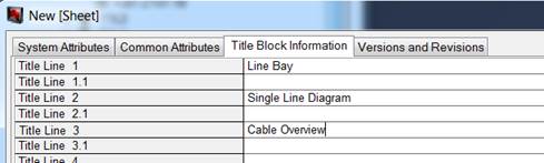
7. Close the dialog New [Sheet], and call the sheet in Visio.
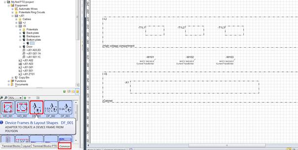
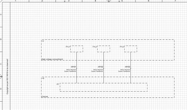
8. Enter one polygon each for the high-voltage compartment and the cabinet (see Entering units in the sheet).
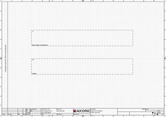
|

|
Use the graphic editing aids such as Dynamic Grid, Guides and Align (see Placing shapes)
|
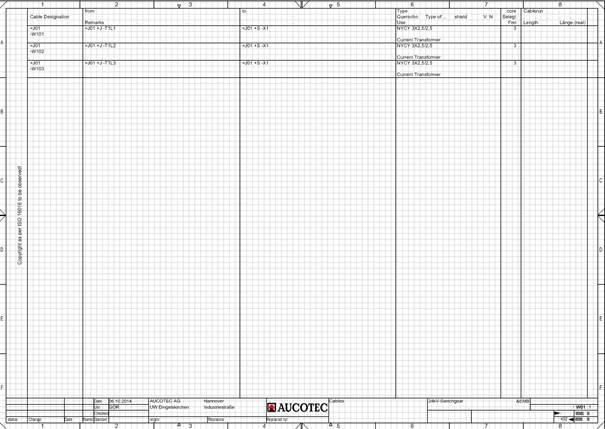
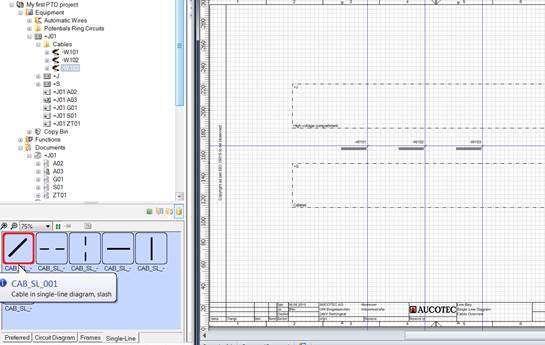
9. The interfacing of the current transformers with the current transformer terminal block is done via the 3 cables –W101, ‑W102 and –W103. Enter these cables in the space between unit polygons.
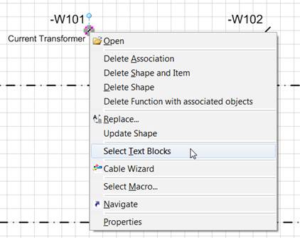
10. The type is to be visible at the cables. How to change a hidden attribute to visible is shown for the "Type Designation" at the cable representations of the general diagram.
· Use the right mouse button at the cable shape to select the function Select Text Blocks.
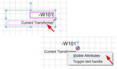
· Click with the right mouse button into the text block framed in red containing Current Transformers, and select Visible Attributes in the context menu.
· From the list of available attributes, drag Type Designation to the right side, and remove the (unlabeled) attribute Cable Type from the list of selected (= visible) attributes.
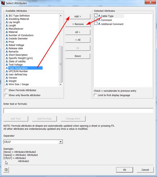
· Then move the Type Designation in this window upward, above the Comment.
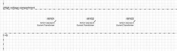
After editing all 3 cables, the cable type information is also visible in the Cable Overview.
11. Enter the target equipment (‑T1L1 to –T1L3 in the high-voltage compartment and terminal block –X1 in the cabinet) as equipment polygons.
The device designation texts must still be moved.
12. Connect the transformers across the cables with the transformer terminal block (see Drawing connections).
If a cable overview is present, then you can create a cable list.
How to create the cable list for the field =J01
1. In the Equipment Explorer, expand the field =J01. Click with the right mouse button on the folder Cables directly under the field.
2. In the context menu, select New Report / Cable List EVU DIN.
This opens the dialog New [Sheet].
3. Enter the Sheet Designation W01, and in the Part of selection dialog select the drawing =J01+S as target folder for the cable list.
4. Click on OK.
This creates the report W01 for the cable list under the drawing =J01+S.
How to open the cable list for the field "=J01"
1. Under the folder Cables in the field =J01, there is now an association with the newly created cable list.
2. Mark the association, and select Open with Visio in the context menu.
This opens the cable list in Visio.