2 The Workflow
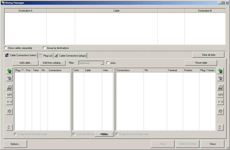
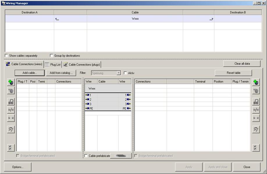
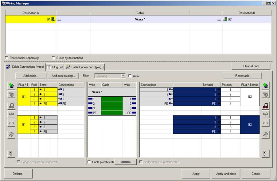
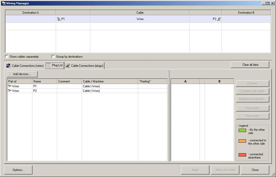
Starting the wiring manager from the equipment folder opens the following dialog:
Press the button Add cable… to select an existing cable, or the button Add from catalog … to create a new cable from catalog data.
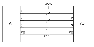
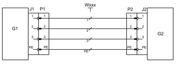
The following example is to be wired:
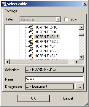
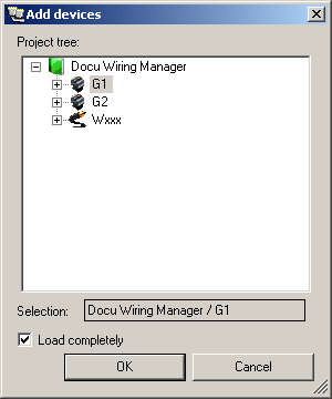
First press the button Add from catalog …to select a cable from the catalog, enter a new name and select the destination folder.
When a new cable is created, it is shown with its cores in the centre of the dialog.
Use the buttons Add Device ![]() and Remove device
and Remove device ![]() to select or deselect devices on the left and right hand-side of the cable for wiring.
to select or deselect devices on the left and right hand-side of the cable for wiring.
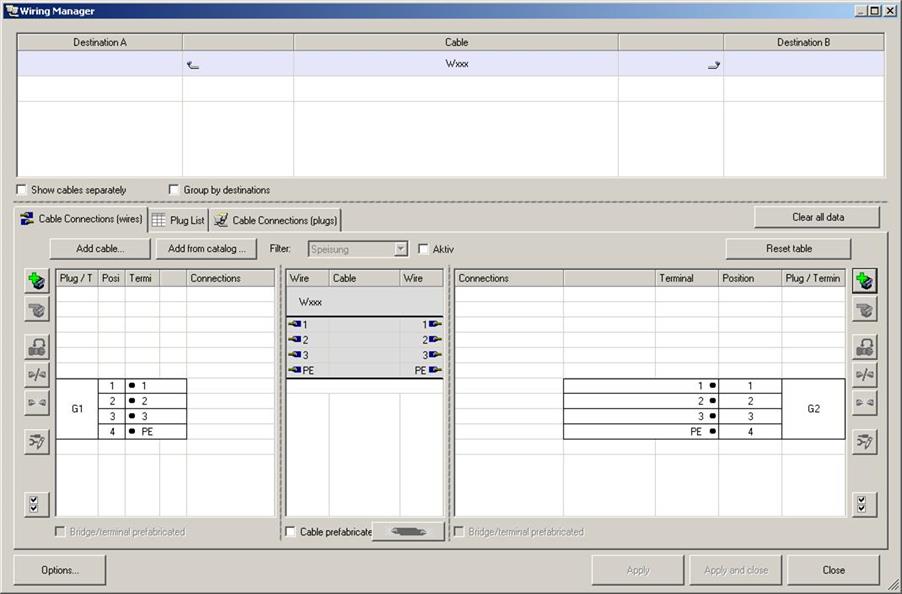
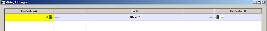
After selecting devices you get the following view in the wiring manager:
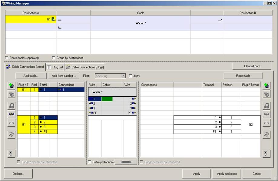
Now the wiring can be started. First mark the left side pin 1 of device G1 and the left hand side of wire 1. Press the button Connect ![]() (on the left) to wire the pin with the left side of the wire.
(on the left) to wire the pin with the left side of the wire.
Repeat this process with all relevant pins and wires. To remove an existing connection press the button Disconnect ![]() . Using the button Select all
. Using the button Select all ![]() you can also select all pins and wires of one side to apply the selection en bloc.
you can also select all pins and wires of one side to apply the selection en bloc.
Use the Ctrl-key to select explicitly a set of pins / wires for wiring. In addition a selection of one wire left and right with one left and right side pin can be applied on both sides simultaneously by pressing the button ![]() .
.
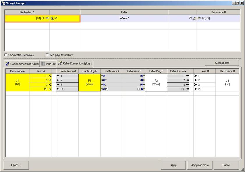
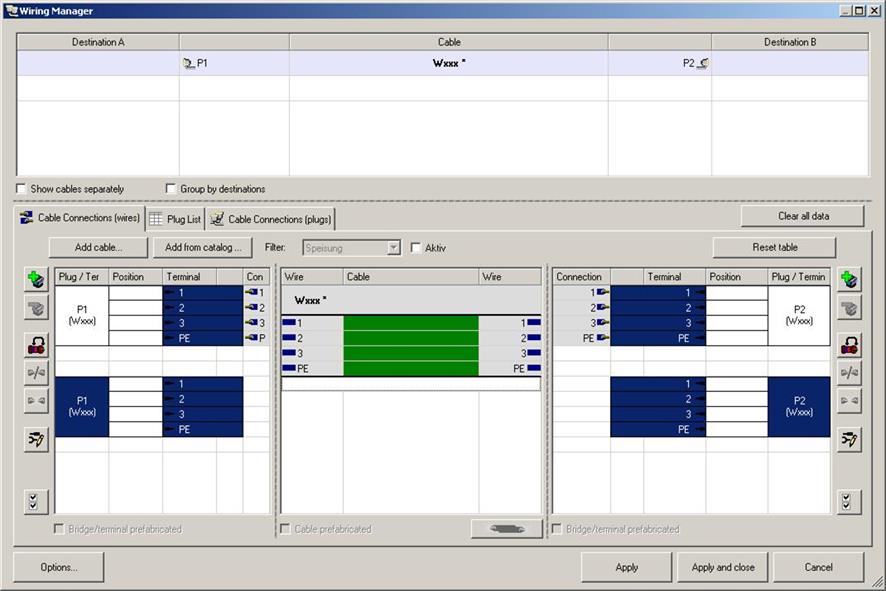
The resulting view after all pins and wires are wired. In addition the top dialog shows the cable and its connected devices.
Here is another example with plugs to devices and cables.
 Proceed as follows:
First wire the cable plugs to the cable.
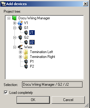
To mount the plugs, switch to the tab Plug list. Main scope of this view is to connect and disconnected cables and/or devices.
To add the device plugs to the list press the button Add Device. Use the Ctrl-Key to select and add several devices.
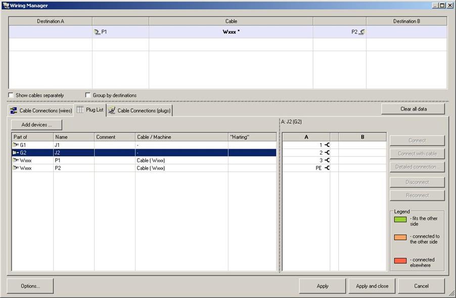
To connect the elements, you only select two relevant items on the left side of the list (Windows – Multi selection – Ctrl + left click). Both plugs are automatically shown aligned in the lower right pane. At first view you can see if both plugs match. For a better understanding a coloured legend is shown.
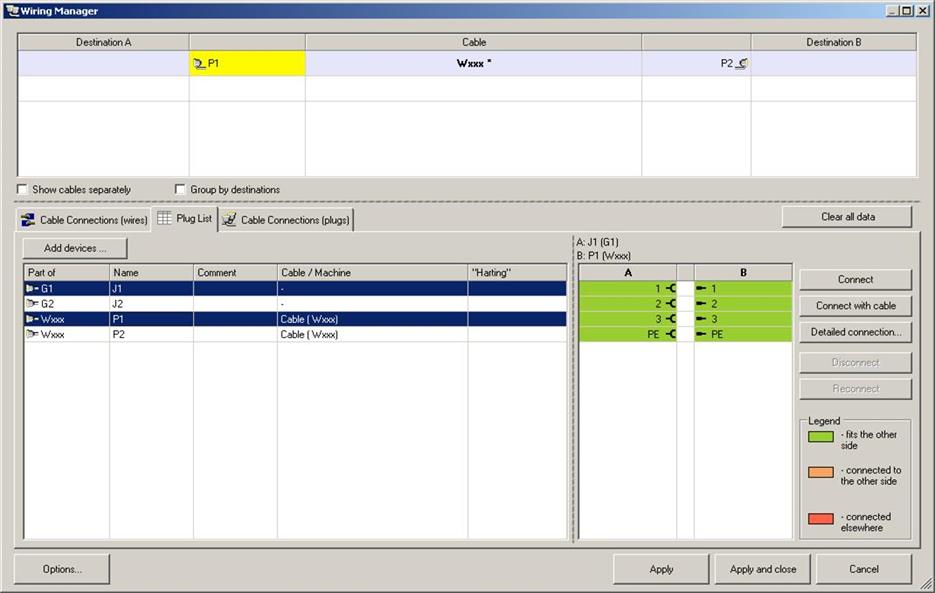
With the Connect button on the right both plugs are stuck together. Only pairs (plug and socket) can be connected directly. If identical connectors are marked (plug-plug; socket–socket) the Connect button is not active.
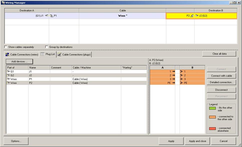
Existing plug-socket-connections can be dissolved with the Disconnect button. Using the Detailed connection... button to move to pin level and possibly rearrange all individual connection data.
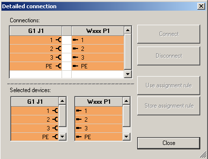
The top area of the dialog shows the real connection, whereas the bottom part shows the pins of the involved plugs. Use the buttons Connect and Disconnect to reorder the connected pins.
The view Cable Connections (plugs) displays the data of a connection. The assembly of a complete connection can be inspected here. Selecting a cable in the upper part of the dialog shows the appropriate information in this tab.
Selecting items below marks the corresponding connection data above and vice versa.