4.2.1 Examples
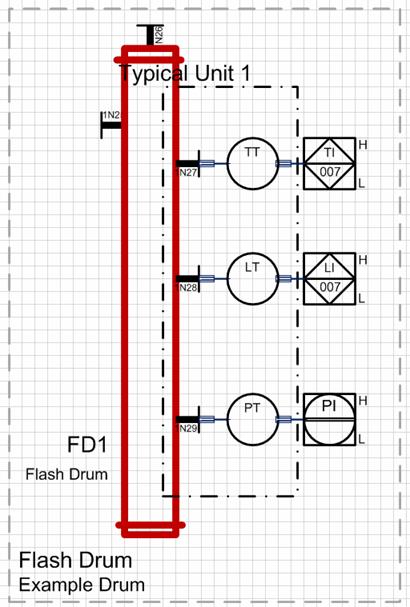
Example1: P&I diagram of a flash drum with optional measurement tags
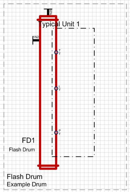
The function .FD from the demo project Instrumentation Standard was used as basis. At the flash drum, up to 3 measurement tags for measuring the temperature (TT), the filling volume (LT) and the pressure (PT) can be defined.
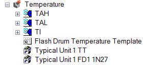
The three sensors are to be defined as function blocks in the typical project.
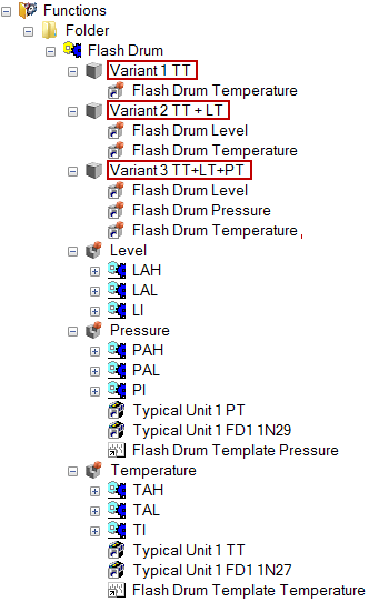
There are to be three possible variants of the flash drum.
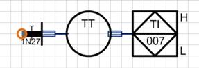
To create the options, the individual sensors are defined as plan components. For this purpose set a source reference point at the connection point of the sensor and the drum. This is assigned the text "TT".
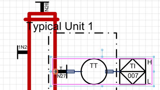
In the project, an option "Temperature" with an associated option sheet "Template temperature" was created. Mark the complete device for temperature measurement in the source sheet and drag it onto the option sheet. In the option sheet, the complete device including reference point is defined as a group.
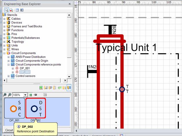
In the source sheet, specify the target reference point instead of the device.
The subfunctions for temperature measurement are moved to the option "Temperature".
If all optional devices are defined as plan components, then the source sheet now only contains the boiler with the three reference points.
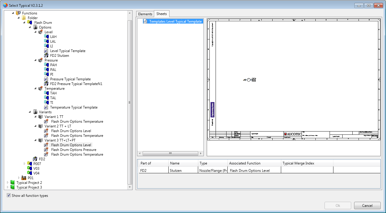
In the typical project, the options are assigned to the three variants.
If the Typical Manager is started with the above typical project, then the variants are shown in the dialog Select Typical.
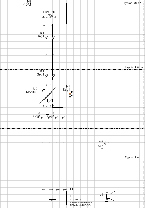
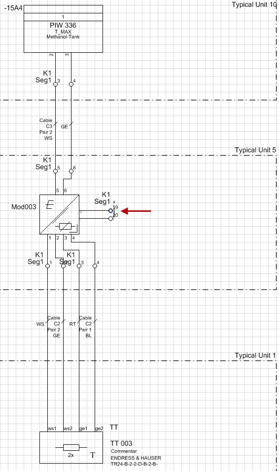
Example 2: loop diagram with temperature meter and optional acoustic signal transducers
Either a loudspeaker or a siren is to be connected to the temperature meter.
In the original plan (loop diagram 2), first of all the variants with loudspeaker (including all associated equipment) were planned.
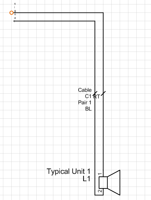
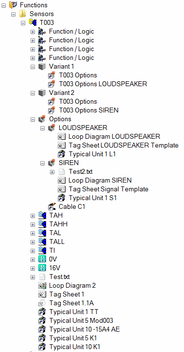
The plan component loudspeaker was moved together with the source reference point "Signal" to an option sheet (loop diagram loudspeaker) that is assigned to the option loudspeaker. All of the pertinent equipment was associated with the option.
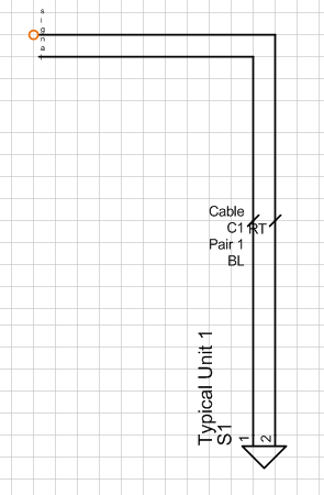
Then the variant with the siren was planned in the original plan, and this plan component was moved together with the source reference point "Signal" to an option sheet (loop diagram siren) associated with the option "Siren". All of the pertinent equipment was likewise associated with the option.
The two options were assigned to 2 variants in the typical project.
In the source sheet (loop diagram 2) the target reference point "Signal" is set at the point where the plan component was separated (at terminal 19 of the terminal block K1).
You can now use the Typical Manager to select the variant of your choice (with loudspeaker or siren). During copying, in an intermediary step the option with the desired variant is copied to the source sheet and this is then transferred into the target project.