4.2 Terminal Block Diagram Open Template
To facilitate graphical changes in the terminal block diagram template or terminal block diagram, an additional module, the Terminal Block Diagram Open Template, enhanced the assistant Terminal Block Diagram. Changes made through this assistant are applied to the XML configuration file describing the terminal block diagram template or terminal block diagram.
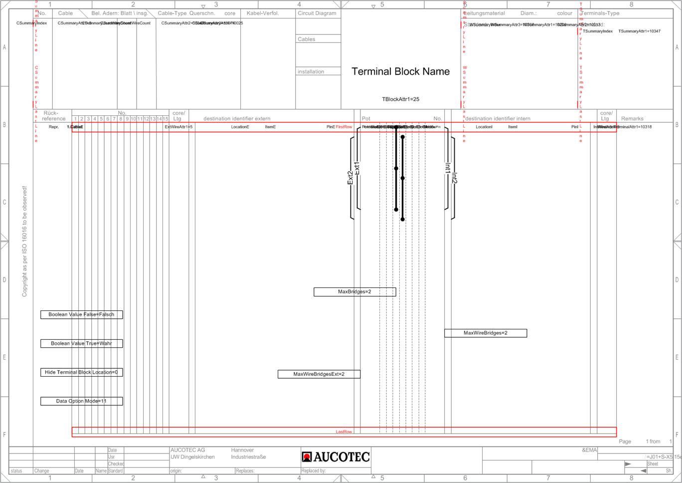
Using this module, you cannot create a new terminal block diagram template, but change the following features of an existing one:
· General changes to graphics aspects such as lines and texts may be applied by editing the template. For this, you have to first unlock the layers and afterwards to lock them again.
· Frames marked in red can be changed in size and position (first line, last line, line width, editable cable width).
· Fields marked in black allow you to change the current values.
· On the left margin of the screen, attributes are listed as examples: You can use these attributes by entering the attribute ID for the information you want to be displayed. This way, you can use attributes of your choice for the terminal block diagram.
· All texts can be formatted according to your choice (font, color, alignment).
How to run the assistant:
1. In the Engineering Base Explorer, select the terminal block diagram template or terminal block diagram.
2. On the shortcut menu, click Select Assistant.
The dialog Assistant selection is opened.
3. Select the assistant module Terminal Block Diagram Open Template, then click Run.
The assistant is started and the Terminal Block Diagram template is opened in Visio.
|
To apply general changes to graphics aspects of the terminal block diagram template like lines and texts. |
Unlock the layers, edit the diagram, and lock them again afterwards. |
|
To add an additional attribute to the template, e.g. for the description of an external device. |
Pull the attribute, in this case ExDevAttr1, from the left margin to the place where the desired information is to be displayed in the template (e.g. set the value of the attribute ExDevAttr1 to 77, if you want to display the additional comment of the external device). |
|
To change the displayed information at an external cable. |
Edit the value of the attribute CableAttr in the template, e.g. from 10437 for material to 25 for commentary. |
|
To change the line width of a terminal. |
Manipulate the width of the corresponding red frame in the template. |
|
To change the maximum number of strap connections that can be displayed in the terminal block diagram. |
Edit the value of the attribute MaxBridges (e.g. set it equal to zero, if you want no strap connections to be displayed) in the template. |
|
To change the maximum number of links that can be displayed in the terminal block diagram. |
Edit the value of the attribute MaxWireBridges in the template. |
|
To control the display of the standard terminal type. |
Terminal Summary Options · = 0: The terminal most used is entered as standard terminal type. · = 1: The predefined standard terminal (attribute standard terminal type at the terminal block) is used as the standard terminal type. If this attribute is not set, the terminal most used is displayed as the standard terminal type. |
|
To control the display if terminals have a cross connection to other destinations; e.g. where the destination of a terminal refers to other destinations.
|
ExtDestInfo IntDestInfo Destination Pin Info=Q Drag the two attributes ExtDestInfo and IntDestInfo from the left margin to the corresponding position of the template. In the terminal diagram, the value specified in the attribute Destination Pin Info is displayed. E.g. Destination Pin Info=Q indicates that the other destinations are represented in the cross connection diagram. |