Home | Using EB | English | Preparations for Outputting Layouts to an NC Automat2 | 1.3 Definition of a Restricted Area
1.3 Definition of a Restricted Area
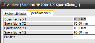
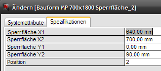
The restricted areas of a mounting plate are described by a data record for general data and one data record each for every restricted area. The restricted areas are defined by specifying 2 X and 2 Y values each. The X and Y coordinates refer to the lower left corner of the mounting plate.
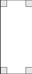
Example: mounting plate with four restricted areas:
|
|
|
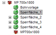
Data record 1 general data (drilling template):
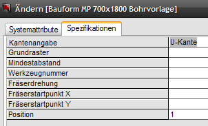
Valid edge specifications for a plate are:
· U edge for a U profile,
· L edge for an L profile or
· None with no edge.
Mounting plate can have different edge profiles. These are available in the U shape, the L shape no edge profile.
This is a specification specific for Perforex!
Data record 2: restricted area_1, lower left
Data record 3: restricted area_2, lower right
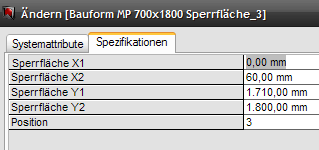
Data record 4: restricted area_3, upper left
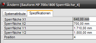
Data record 5: restricted area_4, upper right
The order of the restricted areas in this example is lower left, lower right, upper left and upper right. The sequence is not binding because the result stays the same.