3.1 Starting the assistant
1. In the Engineering Base Explorer, select one of the following objects:
· the Equipment folder or a subfolder
· a unit
· a device
· the Functions folder
· one or several functions.
2. On the shortcut menu, click Equipment Diagram, or click Select Assistant, select the Equipment Diagram assistant and click Run.
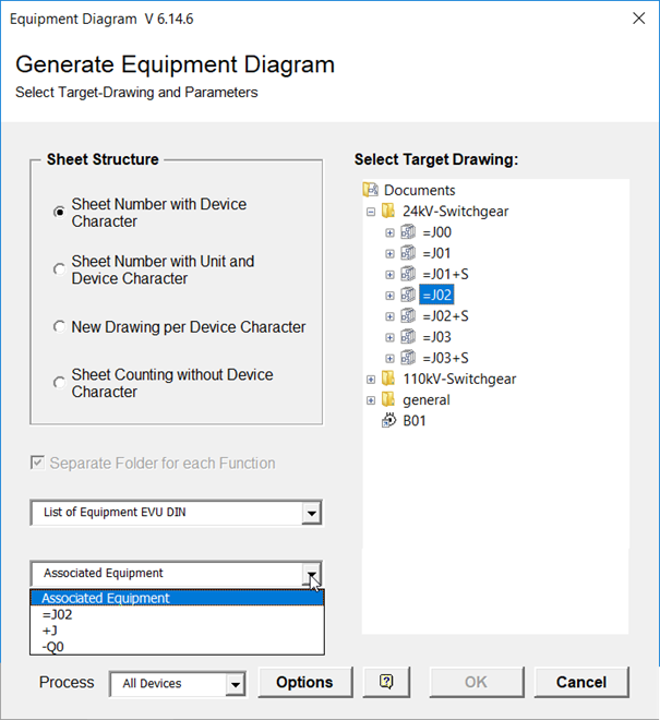
This opens the Equipment Diagram dialog.
The default is:
· Sheet Number with Device Character
· Editing of all Device Characters (all devices).
3. Make the settings as required.
On selecting the target drawing, the sheet template and the associated equipment, the OK button is enabled.
4. Click Options to specify the standard names for the stencils and the various symbols and to define the filter criteria.
5. Click OK to start the generation.
On starting the assistant, the equipment diagrams are created; the progress is displayed in a progress dialog.
Should any errors occur, the error messages are saved under Messages/Equipment Diagram.
|
|
If no target drawing is selected, then the equipment diagrams will be stored directly below the document folder. All equipment diagrams with the selected sheet structure will then be deleted in the document folder even if they have been stored in subfolders or drawings. |
Possible settings
The content of the attribute Device Char is used as device character. If this attribute is void, the device character (first character after the minus sign) is extracted from the attribute Designation.
|
Sheet Number with Device Character |
Only equipment with identical device character is entered into the same equipment diagram. This device character is integrated into the sheet number: "Z" / device character / double-digit serial number: Example: ZF01: All old sheets in the selected target containing in their names the designation character will be deleted automatically while creating the equipment diagram. |
||
|
Sheet Number with Unit and Device Character |
Equipment is sorted according to units (unit designator). Below individual units, the device characters define the sort sequence.
""Z" / unit / device character / double-digit serial number Example: ZSF01: All old sheets in the selected target containing in their names the unit and the designation character will be deleted automatically while creating the equipment diagram. If the attributes Title Line 1 – Title Line 4 are defined at the units, then these will be entered in the sheet when creating the equipment diagrams. In this context the entries of the superordinate units are also taken into account. If e.g. the attribute Line 1 of a subordinate unit does not contain a value, then the attributes of the directly superordinate unit are checked for entered values. If there are none, then the next highest unit will be searched for an entry. This holds analogously for the other title lines.
|
||
|
New Drawing per Device Character |
Only equipment with identical device character is entered into the same equipment diagram. For each device character, a new drawing is created. The sheet numbers are purely numerical. Drawing: "Z" / device character Example: ZF Sheet number: number Example: 1. All old drawings in the selected target containing in their names the designation character will be deleted automatically while creating the equipment diagram. |
||
|
Sheet counting without Device Character |
The equipment is entered serially into the equipment diagrams. The sort sequence is defined by device characters. The sheet number builds like this: "Z" / double-digit serial number Example: Z01: All old sheets in the selected target will be deleted automatically while creating the equipment diagram. |
||
|
Separate folder for each function |
If several functions have been selected on starting the assistant, or if the start is executed on the Functions folder, you can specify that the created equipment diagrams are stored in one sub folder per function. |
||
|
Sheet Template |
The sheet templates of the project are offered for selection. |
||
|
Associated Equipment |
Use the arrow key to select the entry for the Associated Equipment attribute for the equipment diagrams to be created. The following options are available: · the selected equipment in case the Complex Device Level attribute is selected · the selected unit with its superordinate units |
||
|
Process |
Offers the option to select only devices with a specific device character. This selection is not possible if Sheet counting without Device Character is activated. If you start on the Functions folder, you can select a function for the creation of the equipment diagrams. |
||
|
Select Target Drawing |
The target can be a folder or a drawing. Via the shortcut menu, you can create new drawings or subfolders underneath the Documents folder as memory location for the equipment diagram. |