2 Prerequisites
1. The execution requires the Equipment Diagram Assistant. The current version is 6.14.6; it matches EB Version 2020.
2. For the creation, the Equipment Diagram Assistant needs a sheet template that can be selected from the current project templates by means of the user interface. This sheet should have the A3 format, and the preferred shape type should be equipment diagram.
The active sheet area in the equipment diagram template can be specified by a vertical and two horizontal guiding lines. The X and Y coordinates of these lines are used to determine the active area. The distance between the horizontal lines has to be at least 100 mm, otherwise the default insertion point are used. The guiding lines can also be set invisible. If the active sheet area is defined via the guide lines of the sheet template, then the header line can likewise be specified in the sheet template.
3. By default only those items are taken into account that have an entry in the attribute Material Number or Catalog Number.
If none of the attributes is filled, these objects are not taken into account when generating the equipment diagram.
First the entry of the material number is searched, then the catalog number.
4. The item designation must be composed according to the rule [minus sign] code letter count number, i.e. for example -K23 or K241 for a relay. Alternatively (e.g. for numeric designations) an entry of the Device Character in the attribute Device Character is possible.
5. Accessories are currently taken into account only for standard devices. They must be created under the item with the type Other, Accessories.
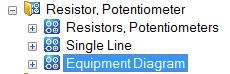
6. The device stencils must be extended by the stencil List of Equipment.
Example resistor, potentiometer:
7. Shapes for the equipment diagram Standard Devices. The symbols are searched for according to the following priorities:
· Preferred symbols DEV1xxx (graphic) and DEV2xxx (cross-references). It does not matter on which stencil these symbols are located.
· If no preferred symbols are defined for the equipment diagram, then the graphic symbol DEV1 is taken from the List of Equipment stencil under the device type in question. Because the cross-reference shape can always be the same, the DEV2 symbol is taken from the List of Equipment stencil under Devices General. If it is not found there, it is also searched for in the List of Equipment stencil under the respective device type.
DEV1 – Base shape
For a list of similar items (same material number, same components), the base shape DEV1xxx is set once. In this shape the technical attributes, the graphic, possibly component data and the representation of the dependent subdevices are defined.
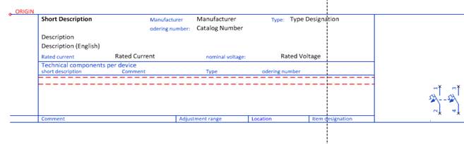
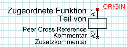
DEV2 – Reference line
A reference line is set for all items underneath the base shapes.
This shape shows the operating data of the respective item and the cross-references to the dependent subdevices shown in the base shape.
![]()
If individual shapes are required for certain items, then the shape names must begin with DEV1… and DVE2... respectively and the shapes must be defined as preferred master shapes.
A Peer Cross Reference must be present for the cross-reference of the "parent symbol" in the reference line and the symbols in the circuit diagram. The cross-references to the "daughter elements" (e.g. contacts) are created via a dynamic area.
Note:
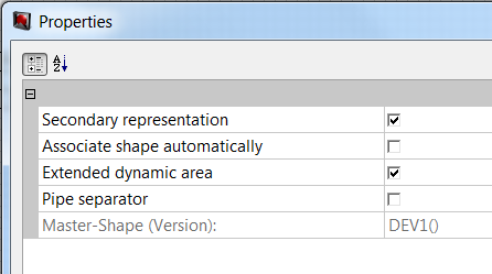
In connection with the data migration it was decided that the base shape does not carry any cross-references and that therefore a reference shape is set also for the first item of a similar group. To make sure that no duplicate reference appears in the circuit diagram, the graphic symbol must have the property secondary representation already in the stencil and is thus excluded from cross-referencing.
Note:
A Peer Cross Reference must be present in the circuit diagram to get a cross-reference to the reference line. This reference type is appended for all symbols with version 6.2.1.
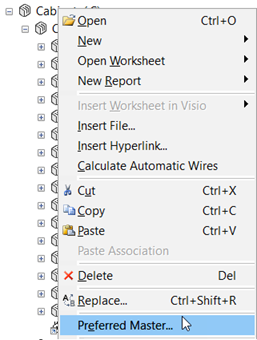
If instead of the standard shapes DEV1 and DEV2 individual shapes DEV1xxx and DEV2xxx are to be used for generating the equipment diagram, then the symbols must be defined as preferred master shapes.
8. Complex devices via typical (multipage)
A typical project must be associated with the working project. The resources of the working project must have
· the text Typical in the Short description attribute (can be set via the assistant)
· an unambiguous designation in the Material attribute.
In the typical project, the devices must have the above-mentioned material entry as their name, and all corresponding sheets must be associated with the device.
9. Complex devices via symbols (one page or multipage)
The associated symbol must be defined as preferred master shape, and it must comply with the naming convention DEV3xxx.
10. Complex devices per symbols (multipage)
The symbol of the uppermost element has to satisfy the naming convention of DEV4xxx, this will create a new sheet.
Depending on the structure of the object symbols are expected which correspond to the naming convention DEV5xx or DEV2xx.
The structure of the symbols is as described above; in this particular case, the symbol with prefix DEV2 can contain graphics, a dynamic area or cross-references.
11. Specification of the detail or field level
For the devices, a Boolean attribute Complex Device Level is available. If a large device such as a circuit breaker or disconnector is represented over several levels, then the attribute must be marked on the device level that directly refers to the large device. All subdevices located underneath are not marked.
The target drawings and folders for equipment diagrams also have the attribute Complex Device Level.
· Target drawing on the field level: the attribute Complex Device Level must be marked.
· Target drawing on the device level: the attribute Complex Device Level must not be marked.
On selecting the target drawing in the Equipment Diagram Assistant, the equipment diagrams are created on the field or detail level, based upon the complex device flags (attribute Complex Device Level) of the equipment and the target drawings.
12. Specification of the degree of detail
The degree of detail of the equipment diagram is determined by the selected target.
· At the target (folder or drawing), the flag Complex Device Level is present but not set.
All subdevices are listed where the flag is not present or not set.
· At the target (folder or drawing), the flag Complex Device Level is present and set.
All subdevices are listed where the flag is present and set.
|
|
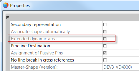
Please note: The representation level is also influenced by the property Extended dynamic area of the equipment diagram shape.
When this property is marked, then also devices nested in subdevices will be shown. |