Cable definition template
Example: cable representation in a standard terminal block diagram
5.1 Standard Terminal Block Diagram
In Engineering Base, the standard terminal block diagram is created in the DIN A3 landscape format. The left-hand area of the terminal block diagram maps the external side of the terminal and the right-hand area the internal side. Externally, maximally 8 cables may be connected, internally maximally 5; external bridges are not shown.
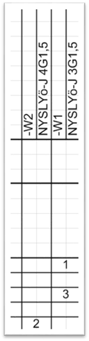
The cables in this terminal block diagram are arranged in columns and lines. The figure below shows the basic mechanisms, and on the right the final result in the terminal block diagram.
|
|
|
|
Cable definition template |
Example: cable representation in a standard terminal block diagram |
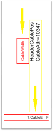
The red box CableWidth shows by means of its size how the two attributes are displayed. The position to the left of the attributes specifies that the cables are entered from right to left. If the red box were positioned to the right of the text attributes, then the cables would be entered from left to right.
The cable attributes (HeaderCablePos and CableAttr=10347) themselves correspond to the entries 1.CableE and 1.CableI, the individual cores of the cable are thus listed under the cable.