2 Creation of a Cause & Effect Table
In Engineering Base, you can describe the various causalities in a C&E table. To create that table, carry out the following steps:
· Define the symbols for causal relations and votings.
· Define the causalities in a cause and effect worksheet.
· Create and output the cause and effect table via Excel.
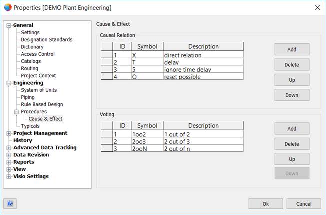
To define the symbols for causal relations and votings
1. Select the project. On the shortcut menu, click Properties.
2. In the Properties dialog of the project, expand the Engineering folder, then expand the Procedures folder.
3. Click Cause & Effect.
This opens the Cause & Effect dialog.
4. Under Causal Relation, define the symbols for the required causal relations.
5. Under Voting, define the symbols for the different votings.
6. Click OK to save your entries.
Meaning of the columns
|
ID |
For the ID, you can choose a value between 1 and 50. Either you enter the ID directly or you select a value using the button |
|
Symbol |
Enter the symbol that is to be used in the C&E table for a causal relation or a voting. |
|
Description |
Enter a description for the defined symbol. |
Meaning of the buttons
|
Add |
Using this button, you can create a new line for the definition of a causal relation or a voting. The smallest available ID is automatically entered as ID. |
|
Delete |
Deletes the marked line in the causal relation or voting area. |
|
Up / Down |
The marked line in the causal relation or voting area is moved up or down in the displayed list. These actions do not influence the ID. |
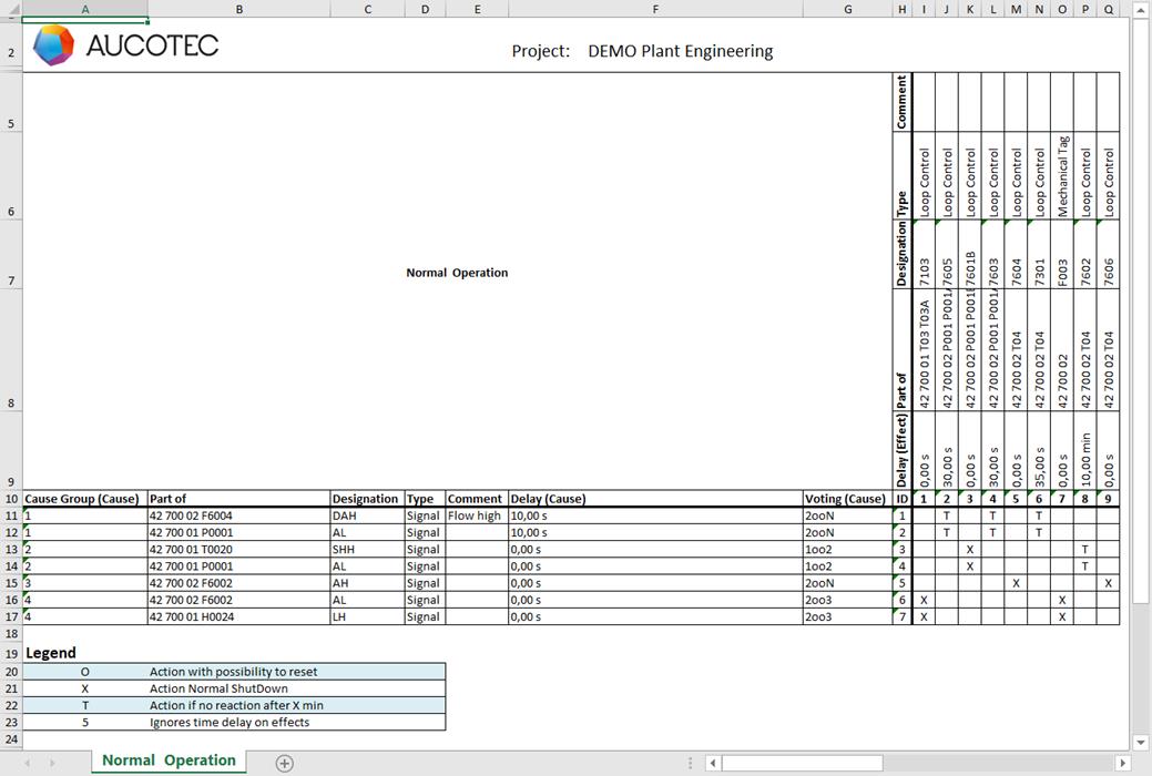
To create a cause & effect table
1. Mark a process and click Procedures on the shortcut menu.
2. Select a worksheet template from the list of available C&E templates.
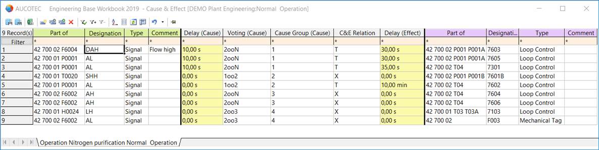
3. Fill in the table. Assign the causal relation and voting symbols (column header highlighted in light gray) of your choice to the cause objects (column header highlighted in green). Define the effect objects (column header highlighted in purple).
4. Save the worksheet via Excel. To do so, click ![]() on the toolbar.
on the toolbar.
5. In the Cause & Effect Editor dialog, select the template of your choice and the storage location.
The temporary folder of Engineering Base is offered as storage location C:\ProgramData\Aucotec\Engineering Base\Tmp\XXX.
The proposed name of the created C&E table is composed as follows: Project name_process name (process for which the C&E worksheet has been created , incl. the names of the superordinate processes).
Click ![]() to define the storage location via a selection dialog. The following options are available:
to define the storage location via a selection dialog. The following options are available:
· The Processes folder
· The Documents folder
· The file system.
6. Click OK to create and save the C&E table.