2.6 Transition between Mounting Plates
To perform a routing between multiple mounting plates, a transition must be generated. The transition can only be made between cable duct segments of the mounting plates to be connected. The transition consists of one pin at each cable duct segment and a “virtual cable”.
|
|
Follow these steps:
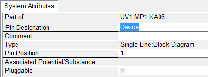
1. In the tree select the cable duct to get a connection on the first mounting plate. Add a pin to the cable duct.
|
|
The type has to be “Single-Line: Block Diagram”.
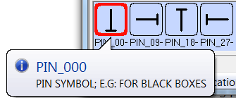
2. Insert the pin at the position in the layout, where the connection should be created. It is possible to use the standard symbols or to create your own symbols.
|
|
3. Using the same principle, add a pin to the cable duct on the second mounting plate where the connection should end.
4. Insert this pin graphically in the layout diagram.
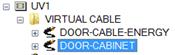
5. Add a virtual cable below the unit which includes the two mounting plates to be connected (e.g. DOOR-CABINET).
6. In the layout connect the two pins with a connector.
|
|
If the two mounting plates are displayed on different sheets, then one connector has to be placed on each sheet at the pin attached with a cable symbol (double graphical representation). |
7. Add the single-line cable symbol to the connector.
If the connector is properly connected to the pins and the cable symbol is placed correctly on the connector, the connection is automatically detected. This may be controlled by editing the cable symbol. The destinations have to be entered correctly.
|
|
A value for the length can be defined for the “virtual cable”. If a wire is routed through this connection, this value is added to the total length of the wire.