2.4 Device Structure
· The devices have to be specified according to the device type.
· The shape “LS_001” should be used for the graphical representation of devices (like mounting plates). A specially designed shape for the device type can be used alternatively.
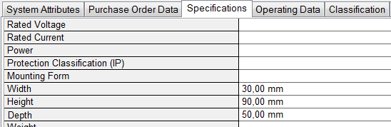
· In the device properties the dimensions must be filled with meaningful values so that the devices are shown to scale in the layout diagram. These values are normally stored in the device master data. In case of deviations the values can be entered manually. Each device has the attributes Width/Height/Depth.
· The attributes of devices have the following meaning:
|
Width |
- the width of device |
|
Height |
- the height of the device |
|
Depth |
- the depth of the device. |
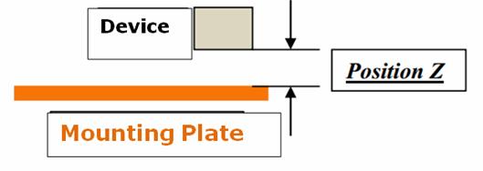
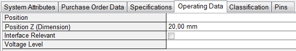
· The attribute Position Z (Dimension) contains the distance of the base of the device to the base of the mounting plate.
|
|
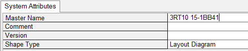
· If a specially designed shape is used, it hast to be drawn and stored in the scale of 1:1. When the shape is inserted, it is scaled accordingly. When storing the shape, make sure that the symbol is stored with Shape Type Layout Diagram.
· It is possible to use complex devices in the layout. For example a contactor with auxiliary equipment. If these additional components are not displayed graphically in the layout, nevertheless the connections of this additional component are taken into account when routing.
The coordinates of the pins refer to the position and orientation of the graphical representation of the main device.