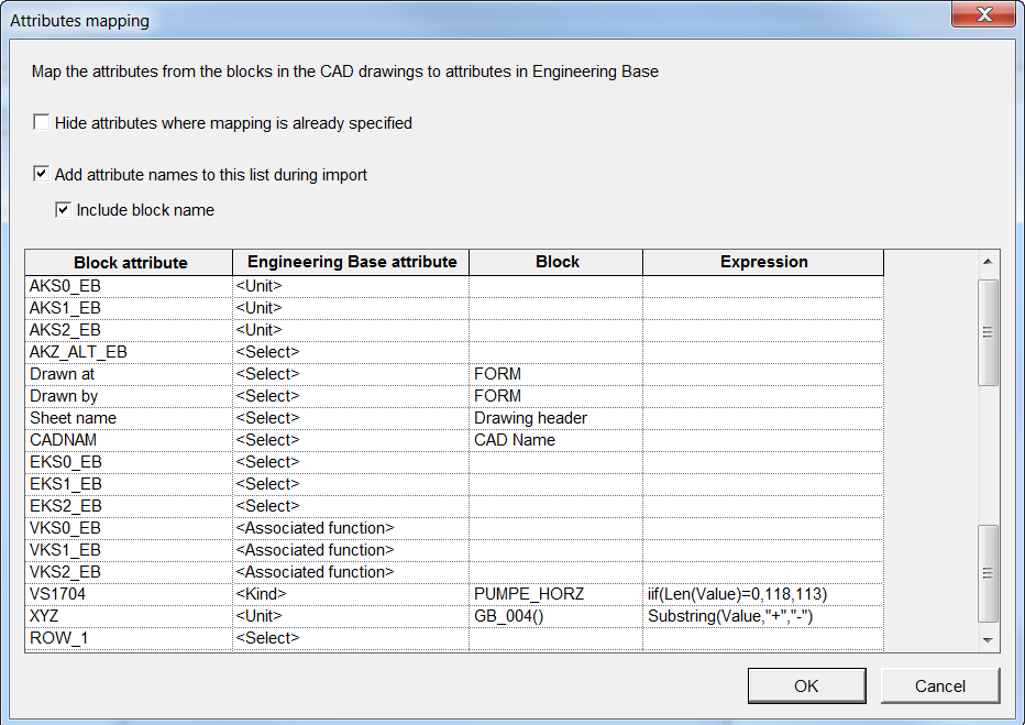
1.1.9 Mapping of Attributes
In this dialog, you can assign the block attributes of the CAD drawing to Engineering Base attributes and thereby create structures in Engineering Base.
All block attributes of the CAD drawings to be imported are displayed in the table.
Click one or more options
|
Hide attributes the mapping is already defined. |
All mappings already known are no longer displayed. |
|
Add attribute names to this list during import |
Attribute names not yet known are added to the list during import. |
|
Include block name |
Block names are displayed in the column Block. If block attributes were already mapped to Engineering Base attributes, and if in the process of mapping no block names were displayed in the table, then, if imported again, the block names do not appear in the column Block. |
Columns and their meaning
· Block attribute: Name of the block attribute in the CAD drawing. By clicking in a row of the column Block attribute, a popup menu may be opened.
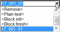
· Duplicate: Duplicates the block attribute.
· Insert: Inserts a blank row in the mapping table.
· Remove: The block attribute is removed from the mapping table.
· Plain text: Some CAD blocks only contain information and no attributes (mostly object designations). With this assignment, the assistant can extract this information and assign it to an Engineering Base attribute.
· Block init and Block finish: The mapping is processed at the beginning or at the end of the block.
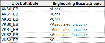
Block attributes with nearly identical names to be assigned to Engineering Base attributes may be combined using the sign "?" (wildcard for one character) or "*" (wildcard for several characters).
|
VKS0_EB |
<associated function> |
|
VKS1_EB |
<associated function> |
|
VKS2_EB |
<associated function> |
|
produces the same result as: |
|
|
VKS?_EB |
<associated function> |
|
or |
|
|
VKS* |
<associated function> |
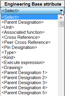
· Engineering Base Attributes: Click a row or column: A list of all Engineering Base attributes (except formula attributes) will be displayed for selection.
|
Engineering Base Attribute |
Meaning |
|
Parent Designation |
If you want to create Engineering Base structures, then this Engineering Base attribute should be selected to get also parent objects of the object filled from the block. |
|
Unit |
The block attribute is assigned to the Engineering Base attribute Unit and the related unit object will be created in the folder structure, if not created, yet. If the attribute is multiply assigned, a respective hierarchical structure will be created below the unit. |
|
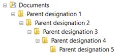
Parent Designation 1-5 |
By assigning a block attribute to this Engineering Base attribute, the sheets created will be stored into a folder structure named by means of the block attributes.
|
|
Associated function |
Engineering Base is searched for a function corresponding to the content of the block attribute. The Visio drawing is then associated with this function. If there is no Engineering Base function with this name, yet, then in the tree below the folder Functions this new function will be created. If the attribute Associated function is assigned multiply, then the respective hierarchical structure will be created below the function. |
|
Peer Cross Reference |
Enables the creation of cross references by assigning sources and drains. |
|
Pin Designation |
Enable the assignment of a block attribute to the Engineering base attribute Pin designation. |
|
Type |
This Engineering Base attribute enables the assignment of a block attribute to a Cover ID. |
|
Kind |
If, depending on its value, a CAD block attribute has to be assigned to different Engineering Base object types (with different Type ID), then Kind has to be used. In the column Expression, a respective condition may be defined. |
|
Drawing |
The assistant creates sheets by default below the folder it was started on. Drawing determines, a folder for drawings has to be created. All subsequent sheets will be stored below this folder. |
If no Engineering Base attribute is assigned, the block attribute will be ignored.
Example:
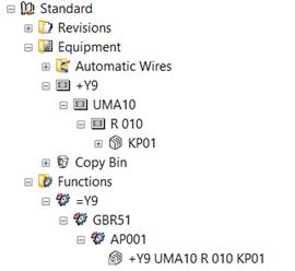
Results in the following structure in Engineering Base:
· Block: A block attribute, if used in several blocks, may have different meanings. Enter a block name, here, and the assignment defined will be restricted to this block. If the column is void, then the assignment is valid for all blocks using this attribute.
· Expression:
· Sometimes, not the complete content of a block attribute is to be transferred. To restrict the block attribute content, all VBA functions plus subsequently listed functions may be used:
o SubString (sString, sFrom, sTo): Copies a sequence of characters from "sString" starting at position sFrom and ending at position sTo.
SubString ("=P1+L1-D1", "+", "-") copies the string in between "+" and "-". This way, the unit may be extracted from the name.
o X: X coordinate of a block
o Y: Y coordinate of a block
o ObjectItem: Returns the reference to create an Engineering Base object.
o AcadAttribute: Returns the reference to an AutoCAD attribute. With the AcadAttribute.Alignment you can check, if the attribute is aligned right or left.
· Import of free texts not assigned to a block.
Using the variables AbsoluteX and AbsoluteY, free texts can be read out and assigned to EB attributes in the source drawing. In this context, the values of AbsoluteX and AbsoluteY refer to the 0 coordinate of the DWG drawing.
Examples:
Left (Value, 5): Only the first 5 characters of the block attribute will be used.
Devices with sub-structure:
If e.g. a terminal -X1 1 has to be imported, then the terminal strip -X1 should be created, too, to enable for storage of the terminal below the terminal strip. To achieve this aim, the block attribute containing the terminal strip name has to comprise the Engineering Base attribute Parent Designation. If the block attribute is not void, then Engineering Base creates a respective parent object terminal strip. If the attribute is void, then using internal procedures the next terminal with defined terminal strip is searched for and the terminal is inserted below this terminal strip.
This approach holds for all structured objects like relay and so on.
Assigning a CAD block to different Engineering Base objects:
A CAD block may be used in two or more Engineering Base object types. Thus, e.g. an attribute X may be used for terminals and pins of black boxes. If the attribute X is used for pins, the attribute value is void. This block attribute has to be mapped to the Engineering Base attribute Kind, then. With the expression iif(Len(Value)=0,118,113) the assignment is done. This means, if the attribute value is void, that is = 0, then an object with type ID 118 (Pin) has to be created, an object with type ID 113 (device), otherwise.
Importing Pins:
Importing pins, it is essential to map layers containing connections in a correct way (see Mapping of Layers). Once this is done, the assistant automatically identifies the intersections of blocks and connections, and creates automatically pins at these positions. The pin type has to be specified in the mapping of layers. If there is a text close to one of these intersections, the text is used as pin designation. If the closest text is not the pin designation, but is contained in a block attribute, then this attribute content may be assigned using Pin Designation to the respective Engineering Base attribute.
Importing Free Texts
Free texts are to be adopted from the DWG which are not assigned to a block. The * has to be entered in the column block attribute. Using the expression
iif(((AbslouteX>364 and AbsoluteX<499) and (AbsoluteY>16 and AbsoluteY<20)),Value, "")
the text is adopted from the DWG for which the reference point of the text fields is located within the area of the coordinates 364<X<499 and 16<Y<20. If this text field has no text, no value is entered into the corresponding EB attribute.