8.1 Creating a Layout Diagram
Layout diagrams represent the cabinet design and provide the basic information for genuine routing. They can be easily created in Engineering Base, as described in the following:
How to create a layout diagram for the unit =J01 +S
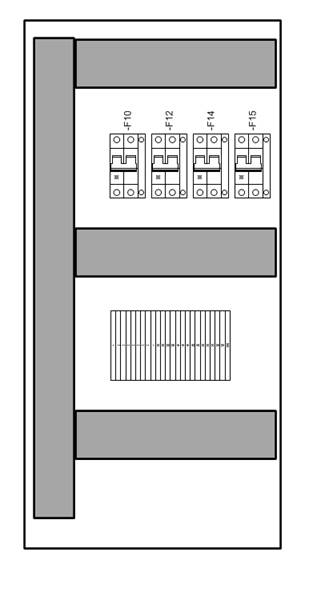
A layout diagram for the cabinet +S is to be created. In order for the cabinet with a width of 32 cm and a height of 66 cm to be represented on a DIN A3 sheet, the sheet shall have a scale of 1:10.
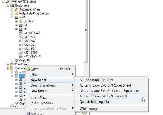
1. In the Documents Explorer, click with the right mouse button on the drawing =J01+S.
2. In the context menu, select New Sheet / A3 Landscape EVU DIN Scale 1:10.
This opens the dialog New [Sheet]. Enter D01 as Sheet Designation, select Layout Diagram as Preferred Shape Type and assign =J01 +S as Associated Equipment.
|
|
The assignment of an equipment object to the layout diagram is the prerequisite for starting a routing run (see following chapter). |
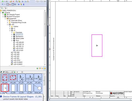
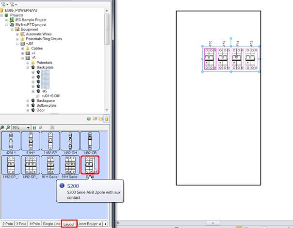
3. The layout of the cabinet backplate is to be shown in the layout diagram. In the Equipment Explorer, mark the object Backplate under the cabinet object. From the stencil Common now displayed, drag the front view for a layout diagram into the graphic.
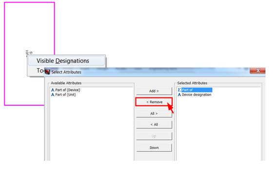
4. Make the information Part of invisible (via the right mouse button at the text).
5. Drag the layout shapes for the automats on the backplate into the representation of the Backplate mounting plate. You can enter several similar pieces of equipment in one go.
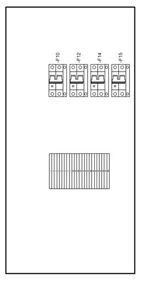
6. Enter the terminal block –X5 under the automats, with sufficient space for a cable duct. For this purpose you must mark all terminals –X5 and drag the layout symbol X_L_001 from the stencil Layout into the location diagram. The result:
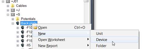
7. Enter the cable ducts in the layout diagram. For this purpose first create the objects in the Equipment tree; it is important to enter the value Cable Duct for the attribute Type.
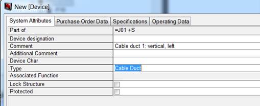
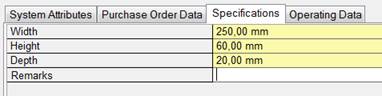
8. Enter the dimensions of the cable duct (tab Specifications).
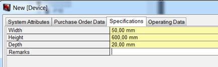
9. Then enter the top, middle and bottom cable ducts. The respective dimensions are:
10. Drag the cable ducts from the Equipment tree into the layout diagram; the graphic is entered from the insertion point using the dimensions of the cable duct. The insertion point is placed centrally on the left-hand side of the graphic.
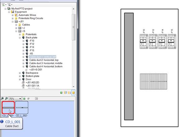
If required move the cable ducts to their proper positions, and make the attribute Part of invisible for all of them.
Result: