9.1.1 Cable harnesses and topologies
To assign the defined wires to the physical cable harnesses, they are represented in a 2-D diagram.
The latter shows the actual connector view, the segments into which the wire harness is subdivided and finally the protections.
The segments contain the length specifications and branch at branching points.
When placing a segment shape on a connection, the Engineering Base Explorer creates a topology folder that contains all segments and branching points of a cable harness.
|

|
The connector shapes have a topology pin, which is used to create the association with the segment.
The branching points can also be equipped with manifolds such as Y pieces.
|
|

|
As an alternative to the connector shapes you can also use shapes for "pin arrangements".
|

Figure 381 Representation of a wire harness
Moreover you can also show information such as
· Component parts of the connector
· Associated Potentials
· Length of the segment
in the 2-D drawing.
|
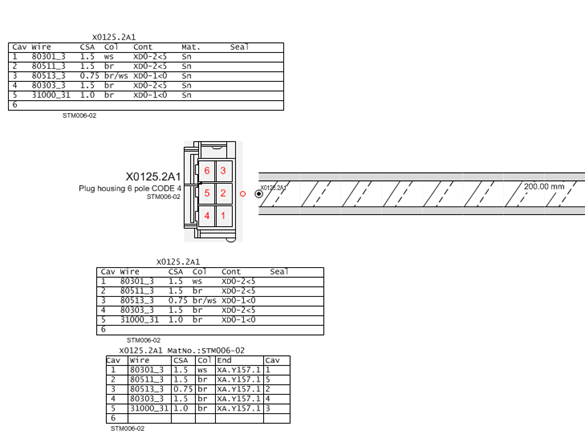
Figure 382 Representation of information in a 2-D drawing
|