![]()
The properties of the E-component should specify at least the comment for the component (tab System Attributes), the part number, the description and the additional description (in each case in the tab Common Attributes).
8.1.2.1 Creating a new E-component
The next step for creating a new E-component consists of editing its properties; for this purpose call the Modify dialog of the component via the button <Edit Properties...>.
Here you fill in the appropriate attribute fields to specify the E-component in more detail.
|
|
The properties of the E-component should specify at least the comment for the component (tab System Attributes), the part number, the description and the additional description (in each case in the tab Common Attributes). |
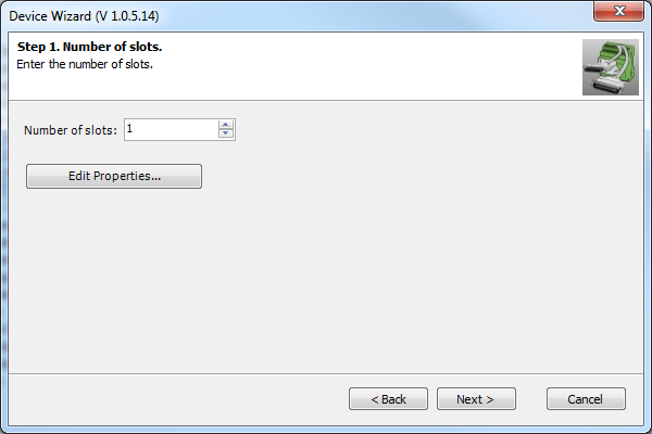
Before you can use <Next> to proceed with the creation of the E-component, you must specify the number of slots to be assigned to it. Enter the desired value either directly in the respective field, or set it with the small arrow keys next to the field.
|
|
You can generate maximally 1,000 slots for the E-component to be created. However, an E-component of that size never occurs in practice. |
|
|
Figure 125 Definition of the properties of the new E-component |
||
Edit Properties
Upon pressing the button "Edit Properties", various dialogs are shown.
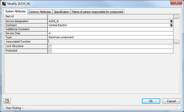
System attributes
|
Figure 126 Modify dialog for a new component (tab System Attributes) |
|
|
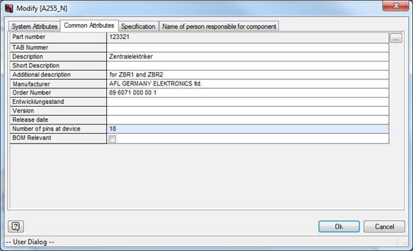
Common attributes |
|
|
Figure 127 Modify dialog for a new component (tab Common Attributes) |
|
|
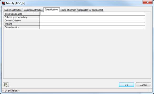
Specification
Figure 128 Modify dialog for a new component (tab Specification) |
|
|
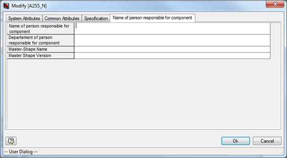
Name of person responsible for component
Figure 129 Modify dialog for a new component (tab Person responsible for component) |
|
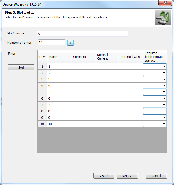
Slots
In the next step, define the slot designation and the pins under the respective slot, separately for each slot.
The pins under the respective slot are listed in the lower area of the window. You can set the number of pins for the slot either directly in the respective field or you can use the plus button next to the field.
|
Slots
Figure 130 Device manager for slots |
Once you have specified the number of pins for the slot, you can define the comment, the nominal current, the potential class and the required finish contact surface of the pins.
The names of the pins are however invariable, always being assembled according to the syntax "slot designation + consecutive number" (only in VOBES environment, see Device Manager Settings (Slot+pin numbers) and Database Key “DeviceWizardCreateAssociations=False”).
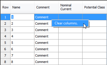
Already existing entries for other pins are overwritten.
This option is however only valid as long as not all cells of the column contain a value.
|
Figure 131 Device manager – Slot definitions |
In the latter case, the option <Clear columns> is available, which can be used to delete all values in the column.
You can delete the contents of a complete column also by clicking on an empty cell.
|
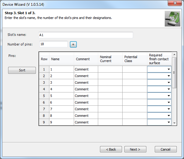
Figure 132 Definition of the slots and the respective pins for a new E-component |
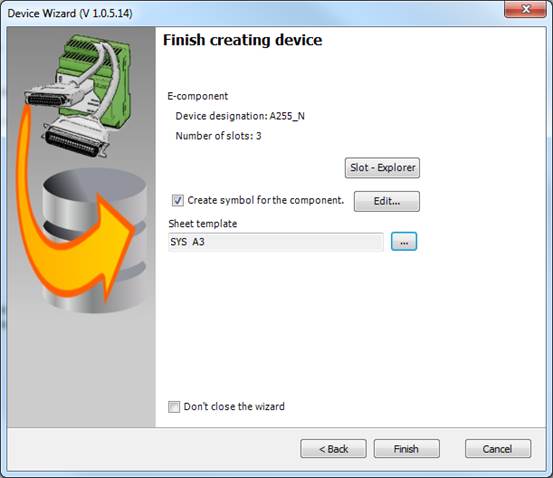
With <Next>, you get to the final window where the device designation as well as the number of slots of the E-component to be created is summarized once again.
Required finish contact surface is read from the specification catalog->Material ->component_pin_surfaces.vec.
Figure 133 Finishing the creation of a component |
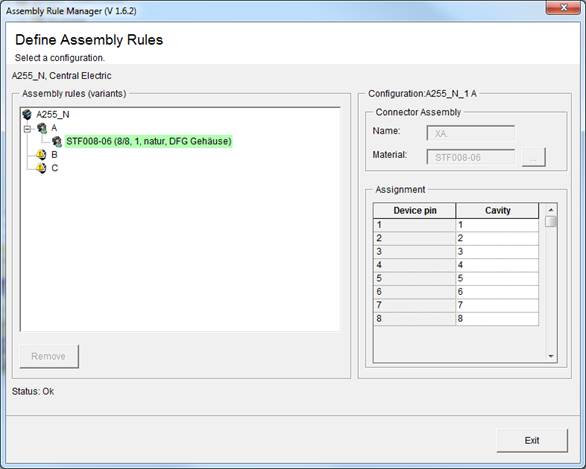
Upon pressing <Finish> for the device, the assembly rule wizard is opened Here you must assign an assembly rule to the newly created component. The assembly rules for library components are stored in the catalog, and those of the prototypes are stored in the project, directly at the prototype component (invisible for the user).
|
Figure 134 Dialog for defining assembly rules |