![]()
You can take the respective information about the connector type from the Modify dialog of the inline connector.
8.17.5.1 Symbol for inline connector cavities
There are several ways for representing the inline connection point cavities. You can use different symbols for male and female cavities (Plugs and Sockets). You can however also use a uniform cavity symbol.
It is up to you which cavity symbols you use.
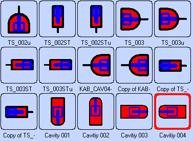
By default the inline connector cavities are located under Stencils -> Devices -> Cavities -> Cavities for inline connection points.
|
|
You can take the respective information about the connector type from the Modify dialog of the inline connector. |
Stencil Devices / Cavity / Inline connection point cavities
|
Figure 236 Symbols of the inline connection point cavities |
Should the representation of the connector cavities be insufficient e.g. for reasons of clarity, you can also display the connectors themselves in the diagram.
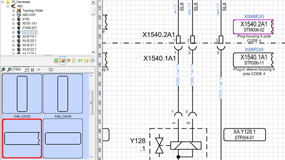
Inline connection point connectors are represented by means of connector boxes placed in the diagram in the vicinity of the inline connector cavities.
Even though from the point of view of electrical planning the representation of the inline connectors is not necessary, yet the connector boxes facilitate the assignment of the individual cavities to the inline connectors and should for informative purposes always be placed.
Likewise you can distinguish whether the inline connection point was placed with all cavities or whether only a part of the cavities is shown.
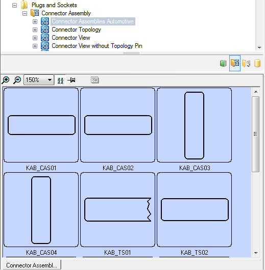
By default the inline connector cavities are located under Stencils / Devices / Plugs and Sockets / Connector Assembly / Connector Assemblies Automotive.
|
Figure 237 Symbols of the inline connectors |
|
Figure 238 Broken-down representation of inline connectors |