2.27 Create a Harness-Topology
After defining and creating the connectors in the wiring diagram (Chapter 2.21), there are already connector objects under the harness. Every connector and splice under the harness should be illustrated in the wiring diagram.
How to illustrate connector in the topology diagram
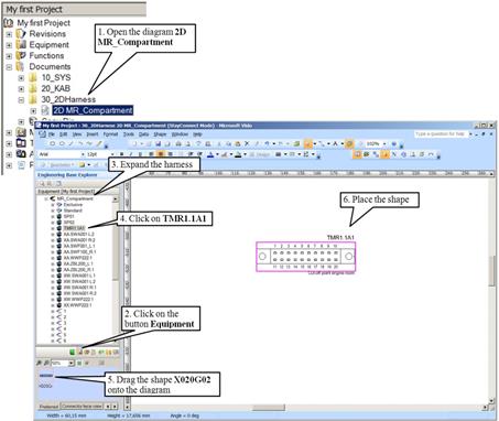
1. Open the diagram 2D MR_Compartment.
2. Change to Equipment in the Engineering Base-Explorer.
3. Expand the folder “30_Harnesses” and “MR_Compartment”.
4. Select the connector TMR1.1A1.
5. Drag the shape “X020G02” from the preview pane onto the diagram.
6. Place the shape.
![]() For rotating or flipping a shape in the diagram, use the Visio actions “rotate” and “flip”. These can be found in the menu bar under “Shape”.
For rotating or flipping a shape in the diagram, use the Visio actions “rotate” and “flip”. These can be found in the menu bar under “Shape”.
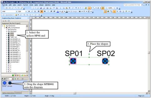
How to illustrate splices in the topology diagram
Splices, similar to connectors, are already arranged under the harness and illustrated in the wiring diagram.
1. Select the splices SP01 and SP02 (holding down the [Shift] or [Ctrl] Key) in the folder MR_Compartment.
2. Drag the shape SPH001 from the preview pane onto the diagram.
3. Place the shapes.
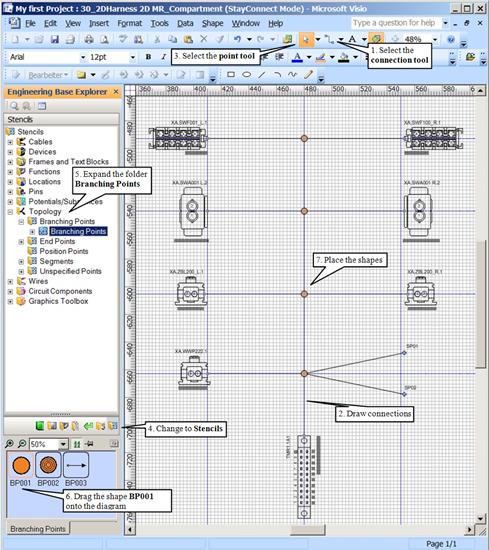
What else should be add to a topology-diagram
Besides connectors and splices, a topology diagram includes segment and connections dots. Connections dots split a segment or create a physical branch of the harness.
1. Choose the connector tool (![]() ) on the opened 2D MR_Compartment diagram.
) on the opened 2D MR_Compartment diagram.
2. Place the cursor at the starting point of the connector or splice (pay attention to the cursor ![]() ), and create a connection (segment).
), and create a connection (segment).
3. Choose the pointer tool ![]() in Visio.
in Visio.
4. In the Engineering Base-Explorer change to Stencils.
5. Expand the folder Topology and Branching Points.
6. Drag the shape BP001 from the preview pane onto the diagram.
7. Place the shape.
Exercise: Complete the 2D-diagram and place the missing connectors:
XA.SWA001 L.2, XA.SWA001 R.2, XA.SWF001_L.1, XA.SWF100_R.1, XA.WWP222.1, XA.ZBL200_L.1, XA.ZBL200_R.1