7.18 Creation of Connector Diagrams Using the Multi Connector Diagrams Assistant
As of EB 2019, the Multi Connector Diagrams Assistant enables you to also create connector diagrams of one or several connector assemblies (multi connectors resp. inline connection points).
1. For the creation of the connector diagrams, select the connectors in the EB Explorer.
2. On the shortcut menu, click Select Assistant, select the assistant Multi Terminal Block Diagram/Multi Connector Diagram and click Run.
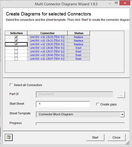
3. Select the connector blocks for which you wish to create a connector diagram.
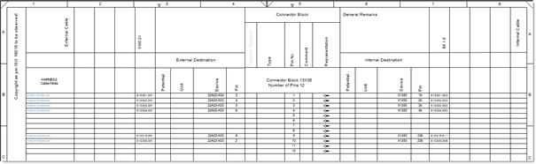
4. Complete the information and select a respective template as a Sheet Template.
The standard terminal block diagram template can be used as a basis for the creation of the connector diagram template.
5. On clicking Start, the connector diagrams are created in the Documents folder. Click Close to end the dialog.
![]() If a connector strip is associated with a function, the newly created connector diagram is also associated with this function automatically.
If a connector strip is associated with a function, the newly created connector diagram is also associated with this function automatically.
Meaning of columns and input fields
|
Selection |
If this column is checked, a connector diagram is created on clicking Start. Already existing connector diagrams are deleted and created anew. |
|
Connector |
Name of the connector |
|
Status |
· Empty: There is no connector diagram yet. · Exists: There already exists a connector diagram. · Created: On executing the assistant, this status is displayed if the creation of the connector diagram has been successful. · Replace: This status will be set for an existing connector diagram if the related checkbox in the Selection column is checked. |
|
Select all Connectors |
If you check this option, all connectors without an existing connector diagram are marked in the Selection column. |
|
Part Of |
Click |
|
Start Sheet |
Provide the sheet designation for First Sheet. First Sheet may be alphanumeric, but has to end with a numeric part. The special characters ".", "_", and "-" are permitted. The created connector diagrams are numbered sequentially (e.g. A1, A2, A3, ...). |
|
Create gaps |
The connector diagrams are not numbered sequentially. In each case, a gap that corresponds to the number of sheets of the previous connector diagram is kept. Example: If the connector diagram A1 has two sheets, the numbering continues with A3. If the connector diagram A2 has five sheets, the numbering continues with A7. |
|
Sheet Template |
Select a sheet template using the selection dialog. |